Una guida pratica alla progettazione che copre la scelta della trave di corsa del carroponte, le tolleranze verticali e orizzontali, i limiti di deriva e deflessione delle colonne, i dettagli di saldatura classificati a fatica, i carichi di frenata e le opzioni pre-ingegnerizzate per capannoni con struttura in acciaio e carroponti da 10–50 t.
Every week, procurement teams across the Middle East, Africa, Southeast Asia, and Latin America send us the same question in slightly different words: they know they need a workshop building, they know they need an overhead crane, and they want to understand how the two decisions fit together. Some have already purchased a crane and now need a building that will carry it safely for decades. Others have secured land and a production plan but have not yet chosen the lifting equipment. In both situations the underlying question is identical: how do you design a steel structure workshop building so that an overhead crane can operate safely, year after year, without the structure cracking, drifting out of alignment, or forcing the crane out of service?
This guide answers that question the way we answer it in daily project work: by walking through the design sequence from the load side down to the foundation side, and by highlighting the decisions that most often go wrong when a workshop is ordered as a generic "steel building" and the crane is treated as an afterthought. It draws on the engineering parameters of the crane-ready workshop buildings we manufacture and export, including a prefabricated crane steel structure workshop engineered for 10–50 ton overhead bridge cranes, a hot-dip galvanized portal frame workshop with 15–36 m clear spans and 5–32 t crane-ready columns, and a multi-span prefab workshop with 2–5 independent bays carrying 5–32 t per bay. Where a figure appears in this article, it comes from those engineering records. Where a figure depends on your specific crane, your site conditions, or your production process, the article says so explicitly rather than guessing.
Table of Contents
- First Principles: What an Overhead Crane Asks of the Building
- Start With the Crane: Capacity, Duty and Span
- What Is an Overhead Crane? Terminology Buyers Should Know
- The Crane Runway Beam: The Component Where Buildings and Cranes Meet
- Clearances: Vertical Headroom and Horizontal Room to Move
- Crane Loads: Vertical, Lateral, Longitudinal and Braking
- Column Drift and Deflection: Protecting the Runway Geometry
- Fatigue Design and Weld Details Under Repeated Crane Action
- Choosing the Frame: Single Span, Portal Frame and Multi-Span Layouts
- Connections and Corrosion Protection in Crane Buildings
- Foundations and the Interface With Your Civil Works
- A Specification Checklist for Workshop Buyers
- Frequently Asked Questions
- Next Steps: Turning This Guide Into a Project
First Principles: What an Overhead Crane Asks of the Building
A workshop without a crane is essentially a covered volume. Its structure must resist wind, snow, and its own weight, and it must stay weatherproof, but beyond that the building and the production process live largely separate lives. A workshop with an overhead crane is a different class of structure. The crane is not furniture placed inside the building; it is a piece of moving plant whose wheels, rails, and loads are carried directly by the building frame. Every lift transfers force into the columns, the roof bracing, and eventually the foundations. Every start-up and braking event shakes the frame laterally and longitudinally. Every wheel passing over a rail joint adds another low-amplitude load cycle that the steel must absorb without accumulating damage.
This is why the design sequence matters so much. If the crane data is known before the frame is designed, the columns can be sized for the true wheel loads, the runway girders can be detailed for the actual rail gauge, and the bracing can be arranged so that traction and braking forces have a short, direct path to the ground. If the crane is specified after the building is ordered, the project inherits whatever geometry the frame happens to have: an eave height that may or may not leave enough hook travel, column spacing that may not suit the crane span, and connections that were never checked for the load cycles a crane introduces. Retrofitting a crane into a building that was not designed for one is possible in some cases, but it is almost always slower and more expensive than designing for the crane from day one, and in many cases it is simply not economical.
The starting point of safe design is therefore a simple statement of intent: the building frame, the runway system, and the crane must be treated as one load path. The following sections walk through that load path component by component.
Start With the Crane: Capacity, Duty and Span
The first document in a well-run crane building project is not the architectural layout. It is the crane data sheet. Three parameters on that sheet drive nearly every structural decision that follows.
Rated capacity
The rated capacity is the maximum load the crane is designed to lift, expressed in tons. In the workshops we engineer, crane capacity typically falls between 5 and 50 tons depending on the building system: the heavy-duty prefabricated crane workshop is engineered for overhead bridge cranes of 10–50 t, while the portal frame and multi-span systems reserve crane capacity of 5–32 t per bay. The capacity figure matters to the structure because the crane's own weight plus the lifted load arrive at the runway as concentrated wheel loads. A heavier crane does not simply add weight; it changes the size and spacing of the wheels, which changes how the load spreads into the runway beam and the column bracket.
Crane duty and working cycle
Two cranes with the same rated capacity can impose very different demands on a building. A maintenance crane that lifts a few times per week stresses the structure in one way. A production crane that lifts heavy loads every few minutes across two or three shifts stresses it in another: more load cycles, more frequent braking events, more heat in the working environment, and a much stronger argument for fatigue-oriented detailing. When buyers ask us to quote a steel workshop design, one of the first questions we ask — after capacity — is how intensively the crane will work. The honest answer shapes the weld class, the connection type, and the inspection expectations for the runway system. It is also a question your crane supplier can answer precisely, because duty classification is part of the crane specification, not a guess.
Crane span versus building span
The crane span is the distance between the centers of the two runway rails. It is usually slightly shorter than the building's internal width, because the crane bridge must clear the columns and the runway brackets on each side. This means the crane span and the building span must be coordinated, not chosen independently. In our portal frame workshop system, clear spans of 15–36 m give production teams a wide field to place machinery and traffic routes; once the required crane span is known, the frame geometry is fixed around it. In multi-span buildings with 2–5 independent bays, each bay can carry its own crane of 5–32 t, which allows different production lines to have different lifting capability under one roof.
What Is an Overhead Crane? Terminology Buyers Should Know
Because crane terminology varies across markets, it is worth aligning vocabulary before the design conversation deepens. The following definitions reflect how the terms are used in international crane practice and in our own project correspondence.
What is an overhead crane? An overhead crane is a lifting machine that travels along elevated rails, usually mounted near the top of the building's side walls, and lifts loads with a hoist that moves along a bridge spanning the building width. Because it works above the production floor, it does not occupy floor space the way mobile equipment does, which is one reason it is the default choice for steel workshops, machine shops, and fabrication halls.
What is an overhead travelling crane? This term describes the same family of machines — an overhead crane that travels along the runway. In many markets "overhead travelling crane" is simply the formal name for what buyers colloquially call an overhead crane. The abbreviation EOT (electric overhead travelling) crane is also common in specifications.
What is a bridge crane? A bridge crane is an overhead crane whose lifting hoist rides on a bridge that crosses the building from one runway to the opposite one. The bridge moves longitudinally along the runway; the hoist (trolley) moves across the bridge. Together, the two motions plus the vertical hoist motion let the hook reach any point in a three-dimensional volume above the floor. When buyers ask what is a bridge crane, the short answer is: it is the standard overhead crane configuration for workshops with two parallel runway beams.
What is a girder in a crane? The girder is the main horizontal beam of the crane bridge — the member that spans between the two end trucks and carries the trolley and the load. In crane building projects you will meet two related but distinct girders: the crane bridge girder, which belongs to the crane and is supplied by the crane manufacturer, and the crane runway beam, which belongs to the building and is designed by the building engineer. Confusing the two in a specification is one of the most common sources of quotation errors.
How does a gantry crane work, and how does it differ? A gantry crane carries its own legs: the bridge runs on legs that travel on rails at floor level, so it does not need a building-mounted runway. Gantry cranes are common in yards, storage areas, and buildings where columns cannot take crane loads. Some projects use both: a gantry crane outdoors for receiving and shipping, and an overhead crane inside the workshop for production. The structural design implications are very different — a gantry crane mostly asks the building for floor space and door clearances, while an overhead crane asks the structure itself to carry the loads.
What is an overhead crane used for? In a steel workshop, the crane's job is to move raw sections, plates, fabricated assemblies, and finished products between stations: from the receiving yard to cutting, from welding bays to machining, and finally to loading. Typical applications in the buildings we supply include structural steel fabrication, machinery assembly, equipment maintenance, and warehousing of heavy goods. Knowing the actual lift path through the building helps the engineer position the runway columns so the crane's useful coverage matches the production flow — a layout question that costs nothing to get right on paper and is expensive to fix in steel.
The Crane Runway Beam: The Component Where Buildings and Cranes Meet
If one component concentrates the engineering of a crane building, it is the crane runway beam — also called the crane girder or runway rail beam. This is the horizontal member supported on each row of columns, at the elevation of the crane rails, on which the crane's end trucks travel. Everything the crane lifts is eventually transferred into this beam, and every alignment problem the crane experiences is either created or solved here.
What the runway beam must do
The runway beam performs four structural jobs simultaneously. First, it carries the vertical wheel loads: when the crane lifts near one end of the bridge, that side's wheels concentrate a large, moving, concentrated load onto one beam. The beam must be checked for bending, shear, and local effects under the worst realistic wheel positions. Second, it resists lateral loads from crane acceleration, deceleration, and the sideway forces that arise when the bridge skews slightly as it travels. These act horizontally and try to bend the beam on its weak axis. Third, it must cope with longitudinal traction and braking forces that push the beam — and through it the whole column row — along the length of the building. Fourth, it must hold the rail accurately: the beam's top flange is the reference plane for the crane's wheels, and small deviations in level or alignment translate directly into wheel wear, skewing forces, and noise.
Sizing follows the crane, not the other way around
The depth and plate thickness of a runway beam are chosen from the crane data — wheel loads, wheel spacing, rail gauge, and duty — together with the column spacing of the building. This is why our engineering workflow asks for the crane data sheet before the frame is finalized. In the prefabricated crane workshop system, runway components are designed around bridge cranes of 10–50 t; in the portal frame and multi-span systems, the crane-ready columns are prepared for runway loads of 5–32 t per bay. These are engineering envelopes, not marketing ranges: within them, the runway beam depth, the bracket connection, and the column stiffening are matched to the specific crane selected for the project.
Rails, fixing and alignment
The rail itself is usually a heavy square-section or crane rail section fixed to the runway beam with clips or bolts that allow controlled adjustment. Detailing matters here: the fixing must hold the rail against lateral and longitudinal forces while permitting the re-alignment that long-term operation may require. Because the beam, its bracket, and the column are one structural chain, our crane workshop designs prepare this chain as a system — bracket position, stiffener layout, and rail fixing are engineered together rather than improvised on site. Buyers comparing suppliers should ask specifically how the runway beam is detailed for the proposed crane, because two quotes can look similar on span and height while differing enormously in the quality of this critical interface.
Clearances: Vertical Headroom and Horizontal Room to Move
Clearance errors are among the most expensive mistakes in crane building design, because they are discovered late — often when the crane is being installed — and they are physically difficult to correct afterwards. Two clearance families must be designed deliberately.
Vertical clearance: how high is high enough?
Vertical clearance is a chain of heights added from the floor upward: the lifting height your process needs under the hook, the hoist and trolley dimensions, the depth of the crane bridge girder, the depth of the runway beam, and finally the roof structure depth. The hook must reach the lowest point of your process (for example, a pit, a machine bed, or a truck deck) and still have travel left at the top; the crane bridge must pass under the roof framing without contact. When clients ask how tall their workshop should be, our answer starts from their process, not from a standard catalog number. In the crane workshop system we engineer, eave heights of 8–15 m cover the great majority of 10–50 t overhead crane applications, from single-level fabrication halls to taller assembly bays with vertical maintenance lifts. The correct figure for your project is calculated backward from the hook travel your process needs, plus the crane's own dimensions, plus the structural depth above the rails.
Horizontal clearance: the space the crane needs to be a crane
Horizontal clearance covers several distinct dimensions that must all be present at once. The crane span must clear the column brackets and any services at the crane's travel level. The end of the bridge must stop short of the end walls by the approach limits the crane manufacturer specifies — the distance within which the hook can reach, and the buffer space the crane needs at each end of travel. The wall side of each runway needs clearance between the crane's extremities and any wall sheeting, cable trays, or piping that runs alongside. And the floor beneath must keep a safe zone free of fixed obstructions where a suspended load will pass. In multi-span buildings, the portal between bays deserves special attention: if a crane in one bay must pass loads toward an adjacent bay's crane, the layout must provide the tandem transfer zone and the headroom it needs.
Crane Loads: Vertical, Lateral, Longitudinal and Braking
Structural design for cranes is, at its core, load-path design. The loads a crane introduces into a building fall into four families, and each family travels a different route to the ground.
Vertical wheel loads
The dominant load is vertical. When the crane lifts a load near one end of the bridge, the wheels on that side carry a large share of the lifted load plus a share of the bridge weight, and this concentrated load moves along the runway as the crane travels. The runway beam experiences this as a rolling concentrated load; the columns experience it as a bracket load that varies with crane position; the foundations receive the accumulated effect at each column. Because the load is moving, the analysis considers the worst positions for each member rather than a single static case. Wheel load distribution between the two ends of the bridge, and between the wheels on one side, comes from the crane data sheet — another reason the crane data must be available before the frame is sized.
Lateral loads
Every time the bridge accelerates or decelerates, the trolley starts or stops, or the crane skews slightly on its rails, horizontal forces act across the building's width. These lateral forces enter the runway beams and push the columns sideways; the roof bracing and the plane of the frame carry them to the ground. Lateral loads also introduce local torsion into the runway beam, which is why crane runway members are detailed with careful attention to the connection between the top flange, the web, and the bracket.
Longitudinal traction and braking loads
When the crane's drive wheels grip the rails and accelerate or brake the bridge, the resulting longitudinal force travels along the runway into the columns and must be braced back to the ground. Over the length of a workshop, these forces can be substantial, and they act on the bracing system repeatedly — every working shift. The design response is to keep the load path short and stiff: longitudinal bracing bays positioned so that traction forces do not have to travel the entire building length before reaching a braced bay.
Impact and dynamic allowance
Crane wheels rolling over rail joints, loads being lifted suddenly, and electromagnetic or mechanical grabs releasing material all introduce dynamic effects above the static values. Design practice accounts for these through impact allowances and through careful detailing of the rail fixing and the beam's top flange. The smoother the runway geometry — straightness, level, and joint quality — the smaller these dynamic effects remain over the building's life, which is why alignment tolerances are a design issue, not merely an installation issue.
A well-designed crane building is therefore never "a building with some extra tonnage." It is a structure whose bracing pattern, column orientation, and connection layout are arranged around a moving load path that changes position thousands of times per year.
Column Drift and Deflection: Protecting the Runway Geometry
Steel is deliberately flexible compared with concrete, and one of its virtues is that controlled flexibility lets structures absorb loads without cracking. But a crane building converts that flexibility into a service problem if it is not bounded: if the columns supporting the runway deflect or drift too much under crane action, the two runway rails stop being parallel and level, and the crane begins to skew, jam, and wear its wheels and rails abnormally. Excessive movement also transfers vibration into the roof and walls, which buyers notice as noise and as cracks in brittle finishes.
Why drift control is a crane issue, not just a comfort issue
Every crane manufacturer specifies limits for how much the supporting structure may deflect under crane loads. These limits exist because the crane's running clearance and wheel behavior assume a geometrically stable runway. When a building frame is designed without crane-aware deflection limits, the structure can pass its own strength checks — nothing yields, nothing breaks — and still provide a runway that is geometrically unacceptable for the crane. The result is a crane that derates itself, triggers skew alarms, or wears out rails years early. For this reason, in our crane workshop engineering the frame is checked for crane-induced movements, not only for ultimate strength: the interaction between frame flexibility and crane operation is part of the design basis.
How design keeps movement bounded
Several measures work together to keep deflection and drift within the limits the crane requires. Column sections in crane bays are selected with adequate stiffness in the direction of the runway as well as across the frame. Bracing is arranged so that longitudinal crane forces reach the foundations through short routes. The connection between the runway bracket and the column is detailed to transfer forces without introducing slack, because connection slip accumulates into alignment loss over time. And the roof plane, which ties the tops of the columns together, is designed so that it assists rather than resists the frame's controlled behavior. None of these measures is exotic; they are ordinary engineering done with the crane's geometry in view. What matters is that they are applied from the start, when they cost nothing, rather than as repairs after the crane starts misbehaving.
What buyers should verify
Buyers do not need to run the calculations themselves, but they should verify three things in any proposal: that the supplier asked for the crane data sheet; that the frame design notes mention crane-induced deflection and drift control; and that the runway columns' connection details are engineered for the specific crane rather than copied from a non-crane building. A supplier who can walk you through these three points in the quotation stage is demonstrating the design discipline this article describes.
Fatigue Design and Weld Details Under Repeated Crane Action
Most loads in a building act occasionally: wind storms arrive, snow falls, and then the structure rests. Crane loads are different in character. A production crane loads and unloads its runway many times per day, every working day, for decades. This accumulation of load cycles brings fatigue into the design conversation — the gradual development of cracks in details that see repeated stress, even at stress levels the steel could safely carry once.
Why weld details are the fatigue battleground
In practice, fatigue in steel structures is governed less by the parent material than by the details: welds, notches, and connection geometry. A smooth plate can carry repeated stress indefinitely at levels where a poorly shaped weld would eventually crack. This is why crane runway design pays close attention to weld classes and detail categories. In our prefabricated crane workshop system, the runway components are fabricated with fatigue-rated welds per GB 50017, the Chinese national steel structure design standard, which classifies connection details by their fatigue performance and prescribes the checks appropriate to each crane duty level. The practical meaning for buyers is simple: the welds in the load path are designed and executed for the load cycle reality of a crane building, not for the occasional-load reality of a conventional warehouse.
Design measures that extend runway service life
Several design and fabrication choices reduce fatigue demand on the runway system. Full-penetration or properly sized welds at high-stress details, ground or dressed where the detail category requires it, reduce stress concentrations. The rail fixing is designed to spread wheel loads into the flange without hard points. Sudden changes of section are avoided along the load path. And the connection between the runway beam and the column bracket is designed so that lateral crane forces enter the column through a stiff, well-defined route. In fabrication, our systems use controlled workshop welding rather than site welding wherever possible — which is also why the portal frame system is built around a zero-field-welding bolted connection philosophy, and why the crane workshop's critical fatigue details are produced under factory conditions where parameters can be controlled and inspected.
Inspection and maintenance expectations
Fatigue-aware design also implies an honest maintenance conversation. Buyers should expect a periodic visual inspection regime for the runway beams, brackets, and rail fixings — looking for any sign of crack initiation, bolt loosening, or rail movement — with the frequency related to the crane's duty. This is normal for crane buildings worldwide and is not a sign of design weakness; it is the correct complement to a structure that works hard. Suppliers who provide an inspection schedule with the delivery documents make this responsibility easy to hand to the maintenance team from day one.
Choosing the Frame: Single Span, Portal Frame and Multi-Span Layouts
With the crane requirements established, the next design decision is the frame configuration. Our workshop range offers three engineered paths, and the choice among them follows from the production layout, the crane plan, and the site.
Heavy-duty crane workshop for 10–50 t bridge cranes
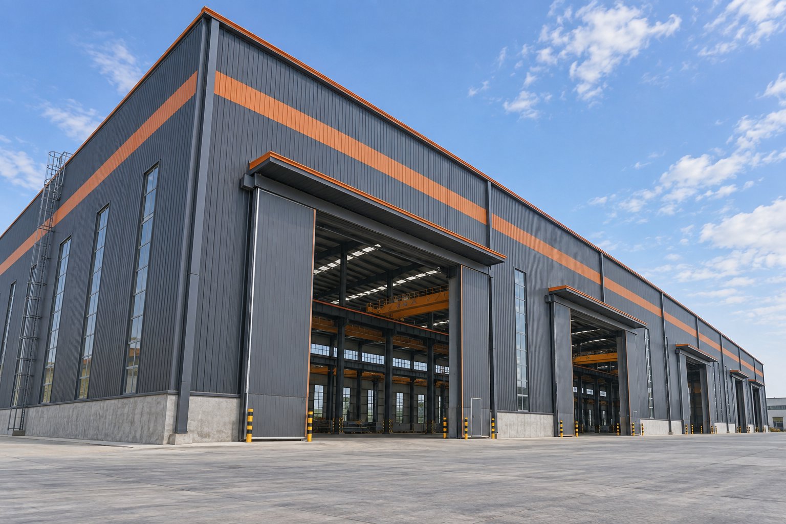
When the process is lifting-intensive — structural fabrication, heavy machinery assembly, and maintenance of large equipment — the dedicated prefabricated crane steel structure workshop is the appropriate system. It is engineered for overhead bridge cranes of 10–50 t, with reinforced columns, eave heights of 8–15 m, and fatigue-rated welds per GB 50017 in the crane-critical details. Delivery runs 30–45 days. This system exists precisely for projects where the crane is the protagonist of the building, and where the frame is designed around the crane's load path from the first drawing.
Portal frame workshop with crane-ready columns
The hot-dip galvanized portal frame workshop covers wide production floors with clear spans of 15–36 m and crane-ready columns prepared for 5–32 t runway loads. Its defining feature is a zero-field-welding bolted connection system: the frame arrives as machined, pre-drilled components that bolt together on site. Production takes 20–30 days after drawing confirmation. This system suits buyers who want generous clear-span production space, a crane in the moderate tonnage range, and the corrosion protection and speed advantages of hot-dip galvanizing and bolted erection.
Multi-span workshop with independent bays
Where the production program includes several lines with different lifting needs, the multi-span prefab workshop provides 2–5 independent bays, each with its own crane of 5–32 t, plus roof daylighting and ridge ventilation for bright, well-tempered halls. Production runs 25–35 days after drawing confirmation. The independent-bay concept matters for safety and economics: each bay's crane loads are designed within that bay's frame, and a line upgrade in one bay does not force re-engineering of the others.
| System | Crane capacity | Key geometry | Production lead time |
|---|---|---|---|
| Prefabricated crane steel structure workshop | 10–50 t bridge cranes | Eave heights 8–15 m; fatigue-rated welds per GB 50017 | 30–45 days |
| Portal frame galvanized workshop | 5–32 t crane-ready columns | Clear spans 15–36 m; zero field welding | 20–30 days after drawing confirmation |
| Multi-span prefab workshop | 5–32 t per bay | 2–5 independent bays; roof daylighting and ridge ventilation | 25–35 days after drawing confirmation |
The table summarizes the engineering envelopes of each system as documented in our product records. Within each envelope, the actual member sizes, connection details, and foundation loads are calculated for your specific crane, site, and process — the envelope tells you which door to enter, not what the final steel weighs.
Connections and Corrosion Protection in Crane Buildings
Crane buildings stress their connections differently from ordinary buildings, so connection philosophy deserves its own design discussion.
Bolted, controlled, inspectable
The repeated, dynamic character of crane loads favors connections that can be tightened to specification, verified, and — if ever necessary — re-tightened or inspected. Bolted connections also align naturally with prefabrication: members are machined and pre-drilled in the factory, where geometry is controlled, and assembled on site with standard tooling. Our portal frame system takes this to its logical conclusion with a zero-field-welding philosophy: no site welding means no uncontrolled heat input, no site-dependent weld quality, and no damage to protective coatings during erection. For crane runway brackets in the heavy-duty system, the bracket-to-column connection is engineered for the specific crane's forces and fabricated under shop conditions.
Corrosion protection that survives the crane's environment
Workshops containing cranes often also contain processes that challenge coatings: humidity, fumes, dust, and occasional mechanical knocks from passing loads. Hot-dip galvanizing, which applies a metallurgically bonded zinc layer to the steel, provides a robust baseline for the frame, and it is the standard protection on our portal frame workshop system. Where the process environment is aggressive, coating selection is reviewed against the actual exposure rather than assumed. There is also a practical interaction to note: because site welding burns zinc and creates local unprotected zones, the zero-field-welding approach protects not only connection quality but also the continuity of the corrosion protection system — one of those details whose value only becomes visible years into the building's life.
Secondary steel and services coordination
A crane workshop also carries services — cable trays for the crane's power, festoon or conductor bar systems along the runway, lighting, and ventilation. Designing the secondary steel and service routes alongside the primary frame avoids the classic retrofit problem of services clashing with crane travel. In the multi-span system, roof daylighting and ridge ventilation are integrated from the design stage, so the environmental strategy of the hall is part of the structure rather than an afterthought hanging below it.
Foundations and the Interface With Your Civil Works
Everything in this article converges at the foundation. The crane's loads — vertical, lateral, longitudinal — pass through the columns into the foundations and the ground. For the buyer, the foundation interface is usually the boundary between two contractors: the building supplier designs and supplies the steel; a local civil contractor builds the foundations. Managing this boundary well is a project-management skill as much as an engineering one, and it starts with clear technical information flowing in both directions.
The building supplier must provide, per column, the design loads and the anchor bolt setting plan — the positions, projections, and sizes of the bolts that connect the steel to the concrete, plus the base plate details. The civil side must return the geotechnical picture: soil bearing capacity, groundwater level where relevant, and any special ground conditions. With both sides of the interface documented, the foundation design proceeds on real numbers. Buyers should schedule this exchange early, because foundation lead time can govern the overall program: steel arrives in 20–45 days depending on the system, and the civil works should be ready to receive it.
Crane buildings add two specific foundation considerations. First, the column rows that carry the runway see larger, more cyclical loads than ordinary building columns, and the foundations should be designed with that duty in view, including the lateral and longitudinal forces from crane action. Second, anchor bolt accuracy matters more: the crane's runway geometry is set by the column positions, and the crane's wheels amplify small deviations at rail level. Our delivery documents include the anchor setting information the civil team needs, and our erection guidance covers the survey and alignment steps that connect civil accuracy to crane performance.
A Specification Checklist for Workshop Buyers
Across many crane building projects, the difference between a smooth procurement and a troubled one is rarely exotic engineering. It is usually whether the right information reached the designer at the right time. The checklist below condenses this article into the items a buyer should have ready — or should insist that the supplier collects — before fabrication drawings are frozen.
- Crane data sheet: capacity, span, duty class, wheel loads and spacing, bridge dimensions, hook approach limits, and rail gauge, from the crane supplier.
- Process requirements: the lifts the process actually performs — loads, frequencies, and the lift path through the building.
- Building dimensions: internal width and length derived from the crane span plus clearances, and the eave height derived from hook travel plus crane and structure depth.
- Frame system choice: heavy-duty crane workshop, portal frame, or multi-span bays, matched to tonnage and layout as described in section 9.
- Runway detailing confirmation: how the supplier's runway beams, brackets, and rail fixings are engineered for the specific crane, including fatigue provisions.
- Deflection and drift criteria: the crane-induced movement limits applied to the frame design.
- Connection philosophy: bolted, zero-field-welding where applicable; corrosion protection matched to the process environment.
- Foundation interface package: column loads, anchor bolt plans, and base details for your civil engineer, plus the geotechnical information you must supply.
- Delivery and erection program: production lead time after drawing confirmation, shipping plan, and erection sequence aligned with civil readiness.
- Inspection and maintenance schedule: the periodic checks for the runway system and connections that keep the crane building safe across its service life.
A quotation that addresses these ten items is a design, not just a price. A quotation that skips them is an estimate that will grow.
Frequently Asked Questions
What is an overhead crane and why is it standard in steel workshops?
An overhead crane is a lifting machine that travels on elevated rails near the top of the building and lifts loads with a hoist on a bridge spanning the width of the hall. It is standard in workshops because it works above the production floor, leaving the ground area free for machines, materials, and traffic, and it can serve the full rectangular volume of the hall with three coordinated motions: long travel, cross travel, and hoist.
What is the difference between an overhead crane and a gantry crane?
An overhead crane rides on runway beams that are part of the building structure, so the building must be designed to carry the crane loads. A gantry crane carries its own legs and travels on floor-level rails, so it does not load the building frame but needs floor space, door clearances, and ground rails. Many sites use both: a gantry crane outdoors for receiving and shipping, and an overhead crane inside the workshop for production.
What is a crane runway beam?
The crane runway beam is the horizontal building member, supported on the columns at rail elevation, on which the crane's end trucks travel. It carries the vertical wheel loads, resists lateral and braking forces, and holds the rail that defines the crane's running line. Its design — depth, connection to the column, rail fixing, and fatigue detailing — is the heart of crane building engineering.
What is a girder in a crane?
In the crane itself, the girder is the main horizontal beam of the bridge that spans between the two end trucks and carries the trolley and load. Do not confuse it with the crane runway beam, which belongs to the building. The bridge girder is supplied with the crane; the runway beam is designed and fabricated with the building. Specifications should name both explicitly to avoid quoting errors.
How does a gantry crane work in a workshop project?
A gantry crane's bridge is carried on legs that travel on rails fixed at floor level. It works by the same three motions as an overhead crane — long travel, cross travel, hoist — but the loads go into the ground through its own legs rather than into the building. In steel workshop projects it is often used in yards and storage areas, or inside buildings whose frames were not designed for crane loads.
What is an overhead crane used for in a typical steel workshop?
Typical uses include moving raw sections and plates from receiving to cutting and welding stations, turning and positioning assemblies during fabrication, loading heavy components onto machining centers, transferring finished products to dispatch, and maintenance lifts on production equipment. The specific lift path through your building should shape the column grid and runway layout at design time.
What crane capacities do your workshop systems support?
Within the engineered envelopes documented for our systems: the prefabricated crane steel structure workshop is designed for 10–50 t overhead bridge cranes with eave heights of 8–15 m; the portal frame galvanized workshop has crane-ready columns for 5–32 t; and the multi-span workshop provides 5–32 t per bay across 2–5 independent bays. Within these envelopes, member sizes and details are calculated for your specific crane and site.
Why does fatigue design matter for a workshop crane building?
A production crane loads its runway many times per day for decades, and repeated stress cycles can develop cracks at vulnerable weld details even when each single load is well within the steel's capacity. Fatigue design — matching weld classes and details to the crane's duty, as our crane workshop does with fatigue-rated welds per GB 50017 — is what keeps the runway system safe over its full service life, supported by a periodic inspection schedule.
Next Steps: Turning This Guide Into a Project
Designing a steel structure workshop for safe overhead crane operation is not a mystery; it is a disciplined sequence — crane data first, geometry and load path second, details and protection third, and the foundation interface last. The buildings we deliver follow that sequence as standard practice: the prefabricated crane steel structure workshop for 10–50 t applications, the portal frame galvanized workshop for wide clear spans with 5–32 t crane-ready columns, and the multi-span prefab workshop for multi-line plants with independent bays. Each product page documents the engineering envelope in detail.
If you are planning a crane building, the most valuable thing you can send us is the crane data sheet and a sketch of your production flow. With those two documents, we can confirm which system fits, propose the frame geometry with crane-aware clearances and drift control, and quote the complete package — structure, runway engineering, corrosion protection, and the foundation interface package for your civil engineer — with a firm production lead time. Contact our engineering team through the inquiry form on any product page, and let's turn this guide into a building your crane — and your production team — can rely on for decades.