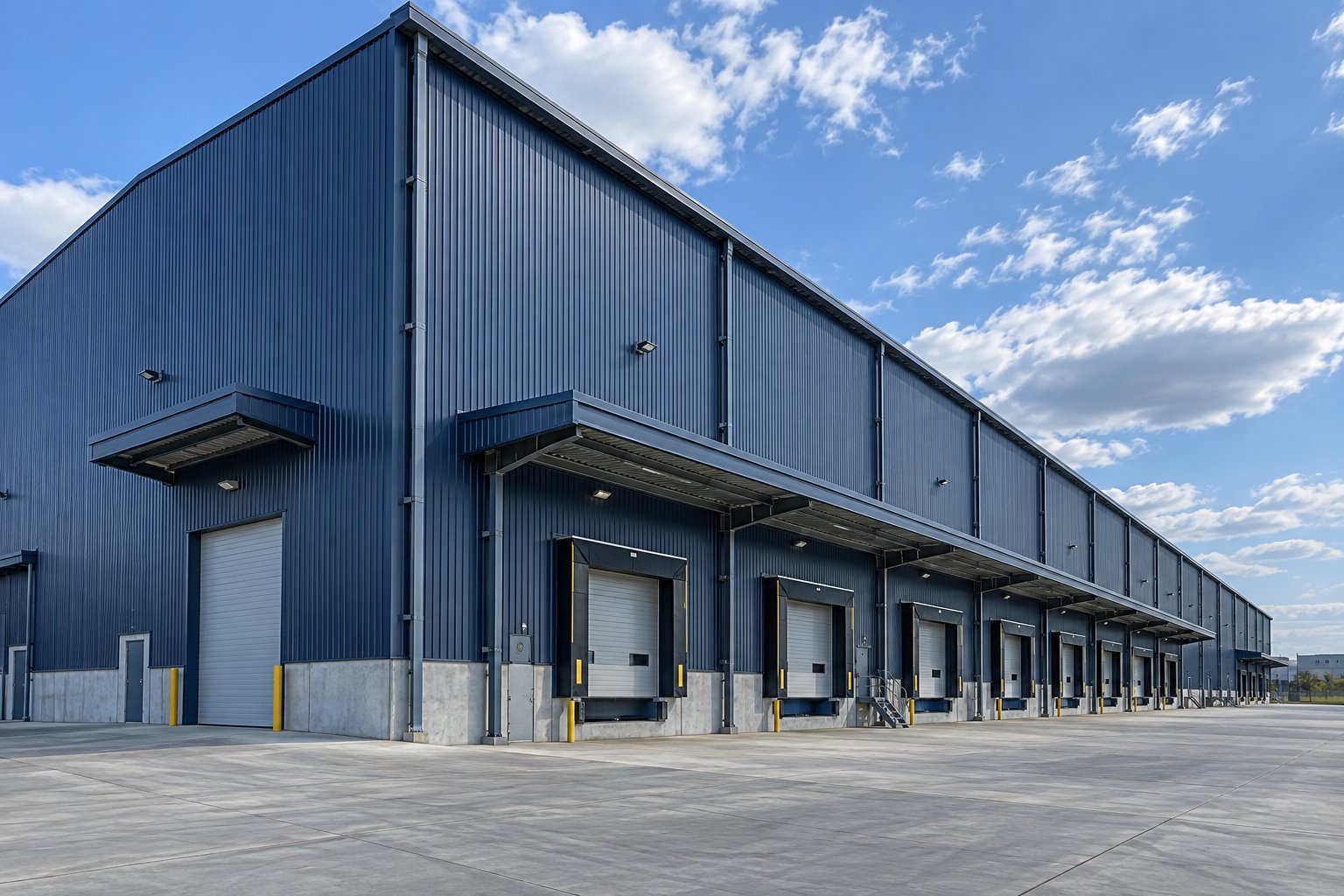
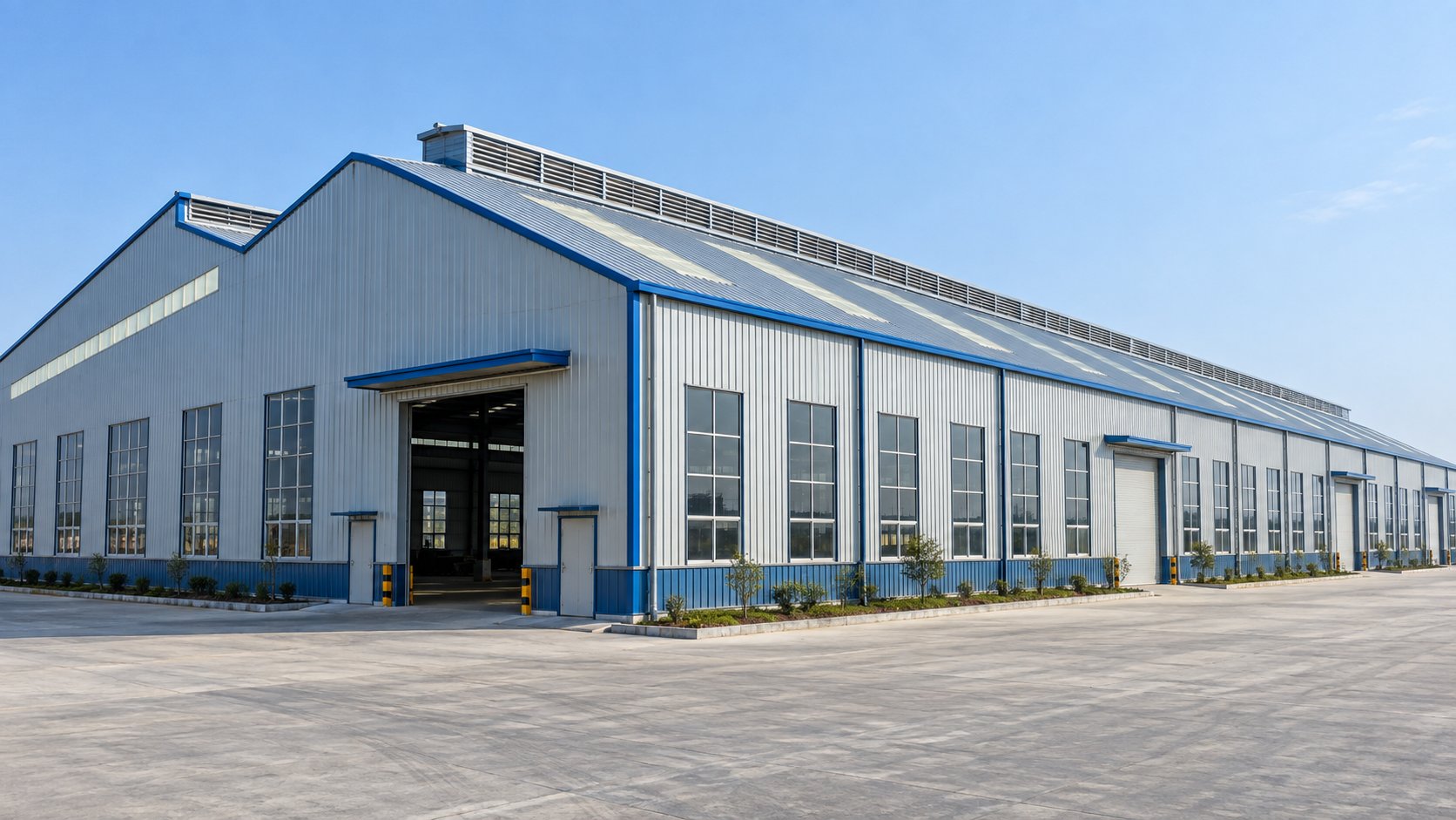
What a Power Plant Building Package Actually Covers
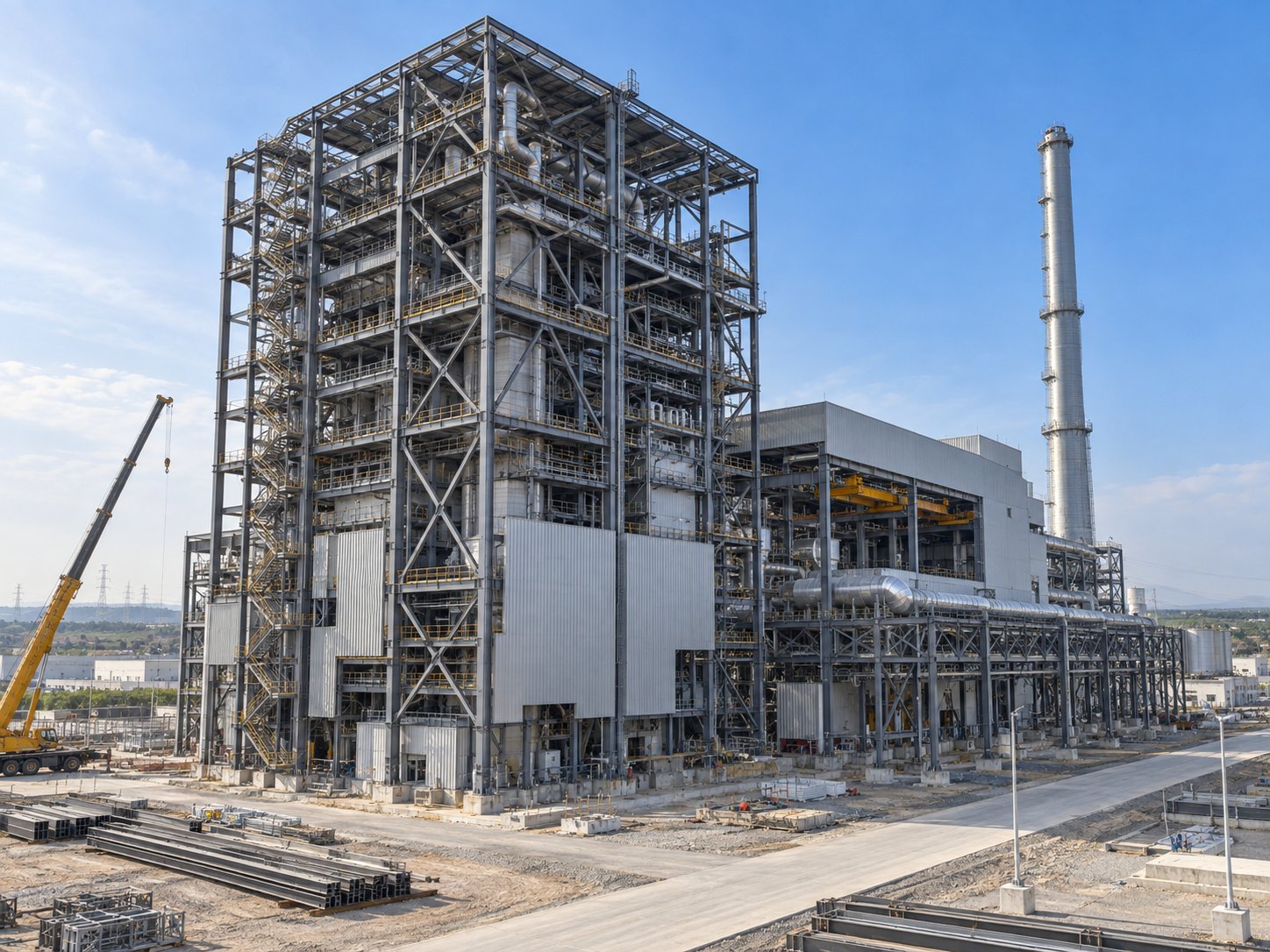
When EPC contractors, owner's engineers, and independent power producers research steel shed building, they are not shopping for a single structure. A power plant is a family of steel structures that arrive in a coordinated sequence: turbine hall, boiler house, deaerator and auxiliary bays, fuel handling galleries, transfer towers, fan decks, and chimney supports, each engineered for loads, temperatures, and erection constraints that ordinary industrial buildings never see. The steel package succeeds when every one of those structures is fabricated to the same tolerance, documented to the same standard, and sequenced to the power island schedule.
Jidian Construction Materials Co., Ltd. fabricates steel structure power plant buildings on its heavy industrial line in Xiamen, Fujian, China, with 360,000 tons of annual steel capacity, the China Steel Structure Manufacturing Special Level Qualification, and welding procedures qualified to ISO 15614-1 with 100% UT inspection of full-penetration butt welds per GB/T 11345. This guide sets out the engineering decisions specific to power plant steel: turbine hall geometry, boiler thermal movement, fuel handling structures, plant-specific loads, materials for hot zones, packaging for heavy freight, and the documentation utilities and lenders demand.
| Structure | Function | Engineering Focus |
|---|---|---|
| Turbine hall | Houses turbine-generator line and main erection crane | Clear span, heavy runway girders, rotor withdrawal path |
| Boiler house steel | Supports boiler and connecting piping | Thermal movement, heavy point loads, buckstay frames |
| Deaerator and auxiliary bays | Feedwater equipment, pumps, switchgear | Operating floor loading, maintenance access |
| Fuel galleries and transfer towers | Conveyor routes from unloading to bunkers | Truss spans, walkways, dust-tight enclosure |
| Fan decks and duct supports | ID/FD fans and flue gas ducting | Vibration isolation, thermal expansion |
Treating these as one coordinated fabrication package-rather than separate purchase orders from separate mills-is what keeps interfaces matching when erection begins.
Turbine Hall Geometry: Spans, Heights, and the Main Erection Crane
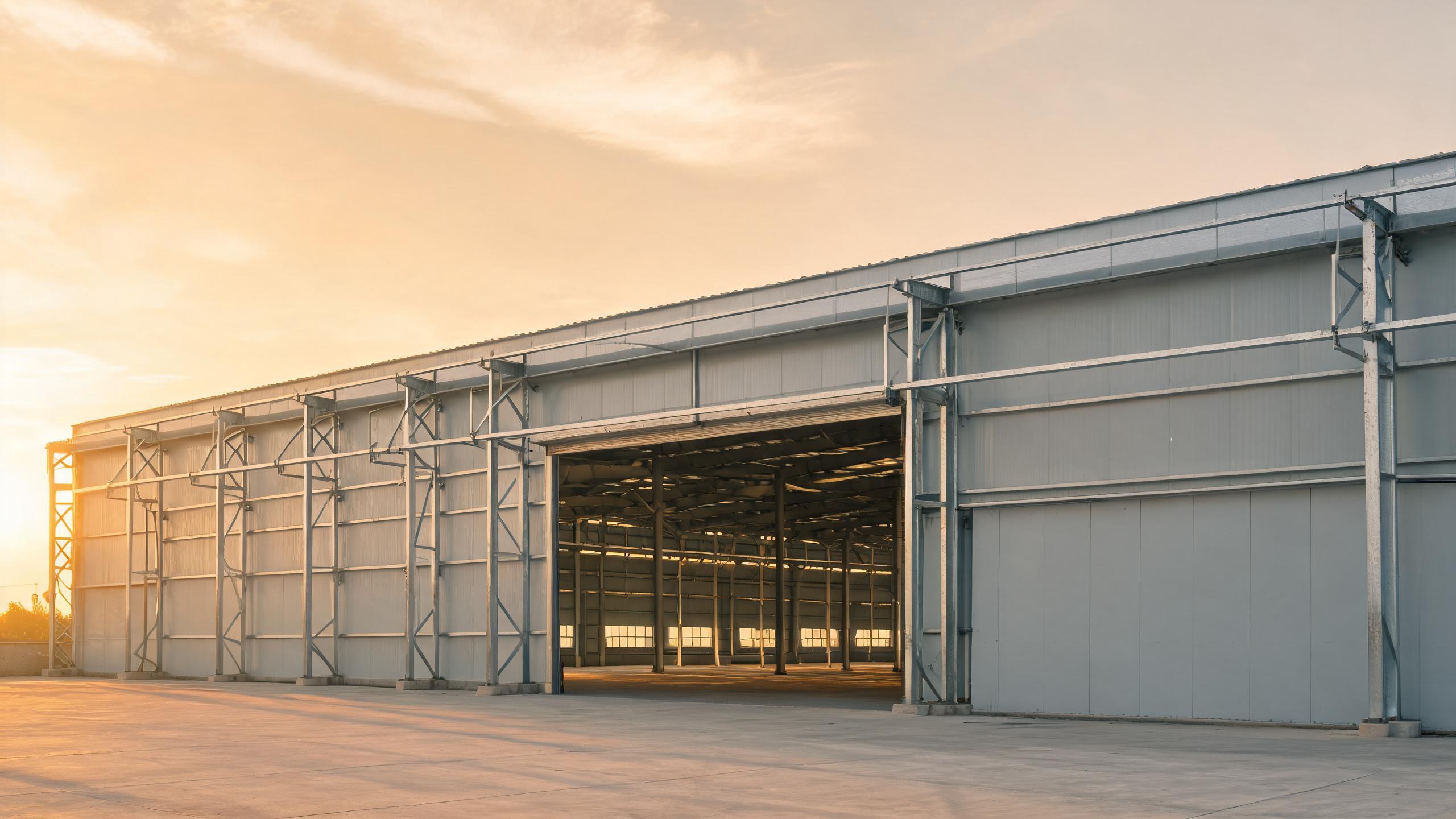
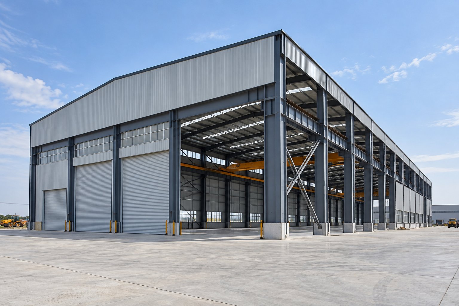
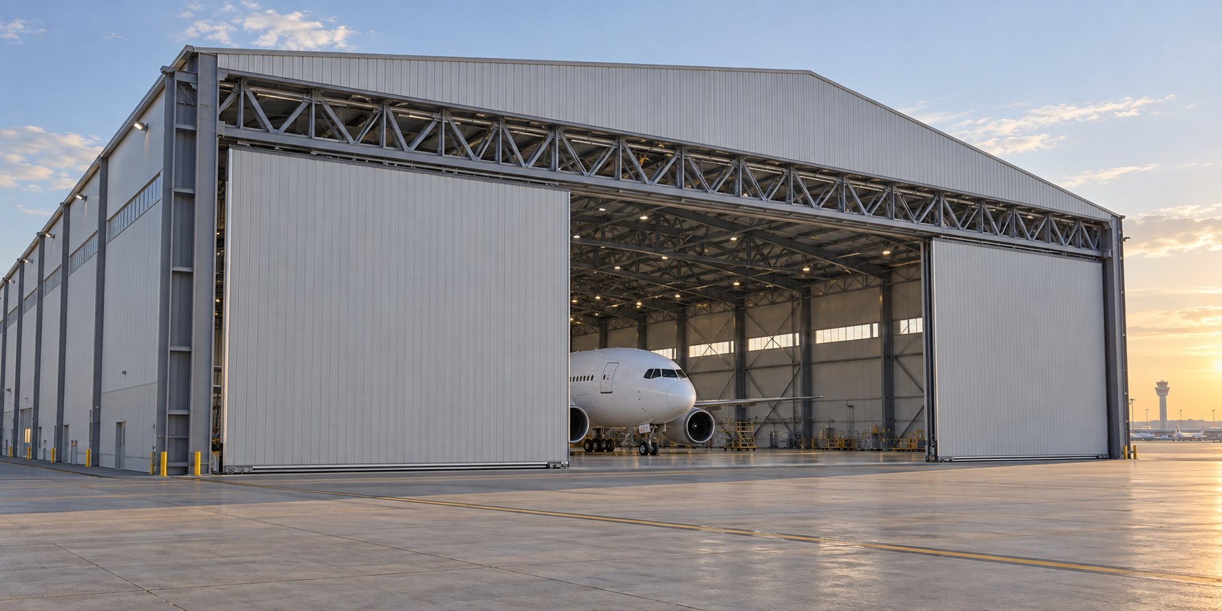
The turbine hall is the signature structure of any power plant. Its clear span is set by the turbine-generator pedestal and the removal paths for the rotor: halls typically span 24-36m clear so the machine line and its surrounding maintenance zone stay column-free. Eave height follows the main erection crane: hook height for rotor lifts, plus bridge depth, trolley clearance, and the headroom needed for tandem lifts during commissioning. Every extra meter of height adds cladding, heating volume, and column weight, so the crane envelope should be fixed with the turbine supplier before steel design begins.
The main erection crane in heavy plants runs at 50-100t class on runway girders integrated into the hall columns-not bolted brackets as in ordinary workshops. Runway girders for this duty are fabricated plate girders with fatigue-sensitive details analyzed per CMAA or EN 13001, and their camber, alignment, and rail tolerances must be held through fabrication and erection. Jidian's heavy industrial buildings carry up to 100t cranes on engineered runway structures, fabricated on German and Italian H-section and girder lines with ±2mm bolt-hole positioning, so rail alignment survives transport and bolted erection without field reaming. The turbine pedestal itself is isolated from the hall structure; the steel frame carries the building and crane loads, while the machine foundation block, supplied by the civil contractor, carries vibration from the turbine line.
Boiler House Steel and Thermal Movement
The boiler house is a live structure: it moves. Boiler steel expands with operating temperature, settles with load changes, and transmits constant pipe forces from connecting systems. The supporting steel is engineered for the combination: vertical point loads measured in hundreds of tons at header levels, lateral forces from buckstay systems that restrain boiler expansion, and thermal displacement accommodated by sliding bearings, slotted holes, and guided connections rather than rigid welds everywhere.
Coordinating these movements with the building envelope is a documentation task as much as a design task. Jidian's engineering package includes structural calculations stamped to the governing code-GB 50009/50017, AASHTO LRFD, Eurocode EN 1991/1993, or BS 5400 depending on project location-with connection schedules that identify every pinned, sliding, and guided joint so the erection crew does not weld a joint the designer intended to slide. Boiler house erection is also sequencing-critical: the steel must reach header levels before pressure parts arrive, which is why phased shipping with drawings keyed to erection sequence matters more here than in any other industrial building.
Fuel Handling: Galleries, Trusses, and Transfer Towers
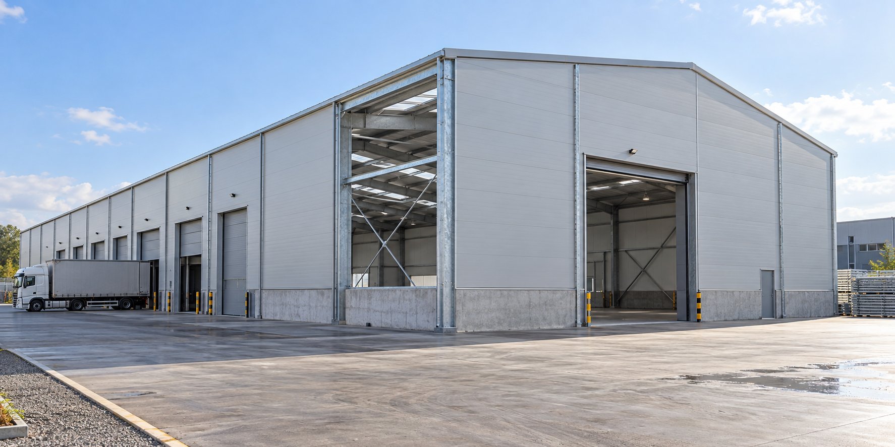
Fuel handling structures are the long tail of a power plant steel package: conveyor galleries spanning between transfer towers, trusses carrying belt loads across roads and waterways, supports for crushers and vibrating screens, and bunker or silo support frames. Each has its own engineering logic. Galleries are enclosed trusses with internal walkways, designed for belt tension, wind on the enclosure, and the dust accumulation loads that fuel type imposes. Transfer towers concentrate equipment loads at changes of direction, so their columns and bracing are heavier than their footprint suggests.
For coal-fired and biomass plants, enclosure tightness is an explicit requirement: fugitive dust is both an explosion risk and an occupational limit, so gallery cladding is specified with sealed joints and maintenance access at every idler station. Corrosion protection in fuel handling is typically upgraded one class above the rest of the site-hot-dip galvanizing at ≥275g/m² per ISO 1461 as a baseline, with ISO 12944 C4 or C5 systems where sulfur-laden dust or coastal air applies. Jidian fabricates these structures to the same tolerance as the main hall steel, because a gallery truss that arrives out of square pushes every support tower along its length.
Loads Unique to Power Plant Structures
Power plant steel carries load cases that do not exist in ordinary industrial buildings, and each one must be specified in the design basis before engineering starts:
| Load Case | Where It Applies | What the Engineer Needs From You |
|---|---|---|
| Pipe rupture and jet impingement | Turbine hall and boiler links | Pipe schedule and rupture analysis from the process designer |
| Ash and dust accumulation | Galleries, bunkers, duct supports | Fuel analysis and accumulation allowance per code |
| Thermal expansion forces | Boiler steel, duct supports | Operating temperatures and movement schedule |
| Seismic OBE and SSE | All structures | Site seismic hazard study with two-level spectra |
| Wind on tall enclosures | Chimney supports, fan decks | Site wind speed and exposure category |
Jidian engineers to GB 50009/50017 as the default basis and to AASHTO LRFD, Eurocode EN 1991/1993, or BS 5400 where the owner's specification requires, with the two-level seismic evaluation handled through the site hazard study your consultant provides. The design basis meeting in week one exists precisely to lock these inputs; changing them after design freeze re-opens member sizing across the whole package.
Steel Grades and Welding for Hot and Fatigue-Sensitive Zones
Material selection in power plant steel follows temperature and toughness. Primary frames use Q345B/Q355B welded H-section with yield strengths of 345-355 MPa per GB/T 1591; secondary steel uses Q235B; and Q345qC/Q370qC bridge steel is available where notch toughness at low temperature is guaranteed-typically outdoor structures in cold-climate sites. ASTM A572 Gr.50 and A36 equivalents can be supplied on request for US-linked projects. Every batch ships with mill certificates documenting chemistry and mechanical properties, and those certificates feed the traceability file the utility will audit for decades.
Welding is where power plant quality is won or lost. Jidian qualifies welding procedures to ISO 15614-1 and certifies welders to ISO 9606, then verifies output with 100% ultrasonic testing of full-penetration butt welds per GB/T 11345, radiographic spot checks at 10-20% on critical joints, and magnetic particle inspection at fatigue-sensitive details such as runway girder web-to-flange joints. The Italian Welding Procedure Qualification Certificate supports CE marking to EN 1090 for European projects. For heavy plate girders in turbine halls, weld sequencing and preheat are controlled to limit distortion, because a girder that arrives twisted cannot carry a crane rail at tolerance.
Fire and Explosion Protection in Power Buildings
Power plant fire protection is risk-based and zone-specific. Turbine hall enclosures face oil fire risk from lubrication and hydraulic systems: deluge and sprinkler zones are coordinated with the structural frame, and cladding in risk zones is specified as non-combustible-A1 rated rock wool sandwich panels per GB 8624 where compartmentation is required. Cable floors and cable risers, the most common fire spread path in utility buildings, are isolated with rated shafts and penetration seals coordinated into the steel scope.
Fuel systems carry explosion venting requirements: bunker and gallery enclosures are designed with vent panels and pressure-release paths so a deflagration vents predictably rather than failing the structure. Chimney and duct supports see both heat and corrosion. The structural steel does not supply the active systems-sprinklers, detectors, and venting hardware come from specialist suppliers-but the frame must carry their loads, accept their penetrations, and hold the rated assemblies they mount to. Jidian's structural package marks every fire-zone boundary and support point on the drawings, so the fire protection contractor designs against real structure rather than assumptions.
Corrosion Protection Against Ash, Sulfur, and Coastal Air
Power plant atmospheres are aggressive: coal dust with sulfur content, ash deposits, demineralized water spray, and for many coastal sites, salt-laden air on top. Corrosion protection is therefore specified zone by zone against ISO 12944 atmospheric corrosivity categories rather than as one site-wide default. Hot-dip galvanizing at ≥275g/m² per ISO 1461 is the baseline for fuel galleries and outdoor structures; painted systems with zinc-rich primer and polyurethane topcoat serve dry indoor zones where color coding and inspection access matter; and thermal spray zinc with sealer handles C4 and C5 exposures on chimney and duct supports.
Coating thickness records ship with every order, because the utility's first major outage inspection will check what was actually applied, not what was quoted. Jidian's shot blasting prepares surfaces to Sa 2.5 per ISO 8501-1 before coating, and every coating batch is logged against piece marks. Specify the fuel analysis and site environment honestly during inquiry-sulfur content and coastal exposure move entire structure groups between coating systems, and the cost difference is far smaller before fabrication than after.
Shipping Heavy Steel: Container and Breakbulk Planning
Power plant steel ships in two regimes: standard frame components fit container envelopes, while heavy girders, deep trusses, and long columns move as breakbulk or flat-rack cargo. The split is engineered during design:
| Component Class | Shipping Mode | Planning Point |
|---|---|---|
| Secondary steel, purlins, cladding | 40ft containers | Nested packing, sequence-labeled bundles |
| Primary frames, columns, braces | Containers or flat racks | Splice locations engineered to transport length |
| Runway girders, gallery trusses | Breakbulk or flat rack | Lifting points, transport frames, port crane limits |
| Anchor bolts and hardware | Containers, iron boxes | Keyed to assembly drawings and bolt schedules |
From Xiamen port, sailing times run 7-14 days to Southeast Asia, 18-28 days to the Middle East and Australia/New Zealand, 25-35 days to East Africa, 35-45 days to West Africa, and 30-40 days to Latin America's west coast. Phased shipments aligned to the erection sequence keep the site from drowning in steel that cannot be used yet-a real failure mode when wharf storage is limited. Trade terms FOB, CIF, or DDP are available; payment by T/T (30% deposit, 70% before shipment), L/C at sight, or Alibaba Trade Assurance.
Erection Sequencing Around the Power Island Schedule
On a power project, the steel schedule is subordinate to one date: turbine generator first fire. Everything backward-plans from it. Boiler steel must reach header level before pressure parts; turbine hall frame must close before the turbine arrives because the main crane erects the machine; galleries must follow conveyor installation, not precede it by months of weathering. Jidian plans shipments and piece marks against that sequence: components are bundled by erection stage, and the assembly drawings show the crane crew exactly which members lift first.
Bolted construction is the method that makes overseas erection tractable at power plant scale. Components arrive pre-cut and pre-drilled to ±2mm on German, Italian, and Japanese production lines, so site crews assemble with standard equipment instead of site welding heavy sections. Jidian dispatches qualified engineers to supervise erection of heavy structures such as turbine halls and boiler steel, and every project receives assembly drawings with piece marks, bolt schedules, and connection sequence videos for critical joints. The practical measure of success is boring: every bolt goes in without reaming, and no member waits on a missing splice plate.
QA/QC, Third-Party Inspection, and Utility Documentation
Utility projects assume third-party inspection, so the quality system must be built for it. Jidian operates under ISO 9001 with CE, SGS, and BV certification, and its in-house inspection team controls raw material quality, ultrasonic inspection of welds, and derusting grade detection before third-party inspectors ever arrive. Mill certificates, weld maps, UT/RT/MT reports, and coating thickness records are compiled per structure and per shipment, and SGS or BV inspectors are welcomed at the factory for pre-shipment checks-a routine Jidian's production planning already accommodates.
The documentation dossier serves three audiences at once: the erection crew that needs assembly drawings and bolt schedules, the owner's engineer who audits calculations and NDT records, and the lender's technical advisor who traces every ton of steel from mill certificate to installed position. Hand over the dossier with the first shipment, not the last: on utility projects, documentation delays clear the way for payment milestones, and the fabricator who cannot produce records on demand stalls everyone's progress including its own.
Comparing Supply Models for Power Plant Steel
How the steel package is purchased shapes everything above. Buying power plant steel as one coordinated fabrication package, rather than as scattered material orders, is what keeps the interfaces true:
| Criterion | Single Fabrication Package | Split Material Orders |
|---|---|---|
| Interface control | One model, one tolerance basis | Mismatches surface during erection |
| Documentation | Unified dossier, single audit trail | Records fragmented by supplier |
| Schedule control | Sequenced shipments against erection plan | Each supplier optimizes its own dates |
| Change management | Priced against frozen revision | Scope gaps become disputes |
Send the plant layout, structure list, design code, and target first-fire date, and Jidian's engineering team returns structural calculations, 3D models, and a tonnage-based price breakdown-free before production-to anchor the comparison on facts.
FAQ
Q: Can you fabricate turbine hall steel with heavy crane runways?
A: Yes. Heavy industrial buildings carry up to 100t cranes on engineered runway structures with fatigue analysis per CMAA or EN 13001, fabricated with ±2mm bolt-hole positioning.
Q: Which design codes apply to power plant structures?
A: GB 50009/50017 as the default, or AASHTO LRFD, Eurocode EN 1991/1993, or BS 5400 where the owner's specification requires, with stamped calculation reports.
Q: How is boiler thermal movement handled?
A: Sliding bearings, slotted holes, and guided connections are engineered into the supporting steel; every pinned and sliding joint is identified on the connection schedule.
Q: What corrosion protection suits fuel handling structures?
A: Hot-dip galvanizing ≥275g/m² as a baseline, upgraded to ISO 12944 C4/C5 systems where sulfur-laden dust or coastal exposure applies.
Q: Do components ship by container or breakbulk?
A: Both. Frames and secondary steel containerize; runway girders and gallery trusses ship as breakbulk or flat-rack cargo with engineered lifting points.
Q: Is third-party inspection supported?
A: Yes. SGS and BV inspection visits are routine, and the dossier-mill certificates, weld maps, NDT reports, coating records-is compiled per shipment for audit.
Q: How do shipments match the erection sequence?
A: Components are bundled by erection stage with piece marks keyed to assembly drawings, so the site receives steel in build order, not storage order.
Q: What steel grades are used in hot zones?
A: Q345B/Q355B welded H-section primary steel, Q235B secondary, with Q345qC/Q370qC bridge steel for low-temperature outdoor structures and ASTM equivalents on request.
Q: How fast can engineering documents be produced?
A: Structural calculations and 3D models arrive within 5-10 working days of receiving the plant layout, structure list, and design basis.
Q: What should the first inquiry include?
A: Plant layout, structure list, governing code, site wind/seismic data, and the target first-fire date-the inputs that let the engineering team price accurately.